This is the first step in creating a fully local AI-powered weather station. In this stage, I’m focusing on displaying sensor data and linking it with visual feedback using RGB LEDs
My goal is to split this Project into multiple small micro projects so this is the Part 1 of the fully local AI-powered weather station.
Parts List
- Raspberry Pi Pico
- DHT11
- RGB LED
- 16×2 LCD Display
- Breadboard
- Dupont wires
Wiring
| Pico Pin | Module | Note |
| GP16 | DHT11 DATA | with pull-up |
| GP 13/14/15 | RGB LED R/G/B | 220Ohm Resistors |
| G0/GP1 | I2C LCD SDA/SCL | LCD I2C Module |
| 3.3V/5V | VCC | Depends on the module |
| Gnd | Ground | common |
Code
Click here to Show the Code
# MicroPython (Raspberry Pi Pico)
# DHT11 -> RGB LED color map: 25°C (blue) .. 40°C (red, hard-capped)
# + 16x2 I2C LCD (PCF8574 backpack)
# Simple algorithm: read -> smooth temp -> LED color + LCD text

from machine import Pin, PWM, I2C
import time
import dht

# ---------- CONFIG ----------
# DHT + RGB LED pins
DHT_PIN = 16          # GP16 for DHT11 data
LED_R_PIN = 13        # GP13 -> Red (through ~220Ω resistor)
LED_G_PIN = 14        # GP14 -> Green (through ~220Ω resistor)
LED_B_PIN = 15        # GP15 -> Blue (through ~220Ω resistor)

COMMON_ANODE = False  # True if your RGB LED is common-anode, else False
BRIGHTNESS = 0.75     # 0.0 .. 1.0 overall brightness
PWM_FREQ = 1000       # Hz

# Temperature mapping and smoothing
TEMP_MIN = 25.0       # °C -> blue
TEMP_MAX = 40.0       # °C -> red (end of gradient)
HOT_CUTOFF = 40.0     # °C and above -> force solid red
SMOOTH_ALPHA = 0.25   # 0..1 (EMA smoothing of temperature)
READ_INTERVAL_S = 1.0 # seconds between DHT reads

# I2C LCD config (PCF8574 backpack)
I2C_ID = 0            # 0 uses GP0/GP1; 1 uses GP2/GP3 by default
I2C_SDA_PIN = 0       # GP0
I2C_SCL_PIN = 1       # GP1
LCD_ADDR = None       # None = auto-scan; or set to 0x27 / 0x3F explicitly
LCD_COLS = 16
LCD_ROWS = 2
# ----------------------------

# -------- Minimal I2C LCD driver (PCF8574 → HD44780 4-bit) --------
# Assumes PCF8574 pin mapping: P0=RS, P1=RW, P2=EN, P3=BL, P4=D4, P5=D5, P6=D6, P7=D7
class I2cLcd:
    RS = 0x01
    RW = 0x02
    EN = 0x04
    BL = 0x08  # backlight bit (active-high on common boards)

    def __init__(self, i2c, addr, rows=2, cols=16):
        self.i2c = i2c
        self.addr = addr
        self.rows = rows
        self.cols = cols
        self._bl_bits = self.BL  # keep backlight ON
        self._init_lcd()

    def _write_byte(self, data):
        # Always keep backlight state asserted
        self.i2c.writeto(self.addr, bytes([data | self._bl_bits]))

    def _pulse(self, data):
        self._write_byte(data | self.EN)
        time.sleep_us(500)
        self._write_byte(data & ~self.EN)
        time.sleep_us(100)

    def _send(self, val, rs):
        hi = (val & 0xF0) | (self.RS if rs else 0)
        lo = ((val << 4) & 0xF0) | (self.RS if rs else 0)
        self._pulse(hi)
        self._pulse(lo)

    def _cmd(self, cmd):
        self._send(cmd, rs=0)

    def write_char(self, ch):
        self._send(ch, rs=1)

    def putstr(self, s):
        for ch in s:
            if ch == '\n':
                self._cmd(0xC0)  # line 2 start
            else:
                self.write_char(ord(ch))

    def move_to(self, col, row):
        base = 0x80 if row == 0 else 0xC0
        self._cmd(base + col)

    def clear(self):
        self._cmd(0x01)
        time.sleep_ms(2)

    def _init_lcd(self):
        time.sleep_ms(20)
        # Reset sequence
        self._pulse(0x30); time.sleep_ms(5)
        self._pulse(0x30); time.sleep_us(200)
        self._pulse(0x30); time.sleep_ms(5)
        # Switch to 4-bit
        self._pulse(0x20)
        # Function set: 4-bit, 2 lines, 5x8 dots
        self._cmd(0x28)
        # Display on, cursor off, blink off
        self._cmd(0x0C)
        # Entry mode: increment, no shift
        self._cmd(0x06)
        self.clear()
# -------------------------------------------------------------------

# Setup DHT
sensor = dht.DHT11(Pin(DHT_PIN, Pin.IN, Pin.PULL_UP))

# Setup PWM on RGB pins
pwm_r = PWM(Pin(LED_R_PIN)); pwm_r.freq(PWM_FREQ)
pwm_g = PWM(Pin(LED_G_PIN)); pwm_g.freq(PWM_FREQ)
pwm_b = PWM(Pin(LED_B_PIN)); pwm_b.freq(PWM_FREQ)

# Setup I2C + LCD
lcd = None
try:
    i2c = I2C(I2C_ID, sda=Pin(I2C_SDA_PIN), scl=Pin(I2C_SCL_PIN), freq=400000)
    addr = LCD_ADDR
    if addr is None:
        found = i2c.scan()
        if 0x27 in found: addr = 0x27
        elif 0x3F in found: addr = 0x3F
        elif found: addr = found[0]
    if addr is not None:
        lcd = I2cLcd(i2c, addr, LCD_ROWS, LCD_COLS)
        lcd.putstr("Weather v0.1")
except Exception as e:
    print("LCD init skipped:", e)
    lcd = None

# ---- helpers ----
def clamp(x, lo, hi):
    return lo if x < lo else hi if x > hi else x

def hsv_to_rgb(h, s, v):
    """h: 0..360, s:0..1, v:0..1 -> r,g,b:0..1"""
    h = h % 360.0
    c = v * s
    x = c * (1 - abs((h / 60.0) % 2 - 1))
    m = v - c
    if   h < 60:   r1,g1,b1 = c, x, 0
    elif h < 120:  r1,g1,b1 = x, c, 0
    elif h < 180:  r1,g1,b1 = 0, c, x
    elif h < 240:  r1,g1,b1 = 0, x, c
    elif h < 300:  r1,g1,b1 = x, 0, c
    else:          r1,g1,b1 = c, 0, x
    return (r1 + m, g1 + m, b1 + m)

def set_rgb_float(r, g, b):
    """r,g,b in 0..1, apply brightness + anode/cathode logic"""
    r = clamp(r, 0.0, 1.0) * BRIGHTNESS
    g = clamp(g, 0.0, 1.0) * BRIGHTNESS
    b = clamp(b, 0.0, 1.0) * BRIGHTNESS
    def to_duty(v): return int(clamp(v, 0.0, 1.0) * 65535)
    if COMMON_ANODE:
        pwm_r.duty_u16(to_duty(1.0 - r))
        pwm_g.duty_u16(to_duty(1.0 - g))
        pwm_b.duty_u16(to_duty(1.0 - b))
    else:
        pwm_r.duty_u16(to_duty(r))
        pwm_g.duty_u16(to_duty(g))
        pwm_b.duty_u16(to_duty(b))

def temp_to_hue(temp_c):
    """
    Linear map for gradient:
      TEMP_MIN -> 240° (blue)
      TEMP_MAX ->   0° (red)
    """
    t = clamp(temp_c, TEMP_MIN, TEMP_MAX)
    span = (TEMP_MAX - TEMP_MIN) or 1.0
    ratio = (t - TEMP_MIN) / span      # 0 at cold, 1 at hot
    return 240.0 * (1.0 - ratio)       # 240 -> 0

# Start LED as blue at boot
set_rgb_float(*hsv_to_rgb(240, 1.0, 1.0))

ema_temp = None

# ---- main loop ----
while True:
    try:
        sensor.measure()
        t = float(sensor.temperature())   # °C (DHT11 is integer; cast to float)
        h = float(sensor.humidity())      # %RH

        # Smooth temperature (EMA)
        ema_temp = t if ema_temp is None else (SMOOTH_ALPHA * t + (1 - SMOOTH_ALPHA) * ema_temp)

        # LED color with hard cap at/above 40°C
        if ema_temp >= HOT_CUTOFF:
            set_rgb_float(1.0, 0.0, 0.0)  # solid red
            hue_info = "RED!"
        else:
            hue = temp_to_hue(ema_temp)
            r, g, b = hsv_to_rgb(hue, 1.0, 1.0)
            set_rgb_float(r, g, b)
            hue_info = "Hue: %.0f" % hue

        # LCD (two lines: Temp, RH)
        if lcd:
            try:
                lcd.move_to(0, 0)
                lcd.putstr("T: %5.1f C      " % t)     # pad spaces to clear leftovers
                lcd.move_to(0, 1)
                lcd.putstr("RH:%3d%%         " % int(h))
            except Exception as _:
                pass

        # Debug print
        print("Temp: %.1fC (EMA: %.1fC), RH: %.0f%% -> %s" % (t, ema_temp, h, hue_info))

    except OSError as e:
        # DHT11 can be finicky; skip this cycle on error
        print("DHT read error:", e)

    time.sleep(READ_INTERVAL_S)
Demonstration Video
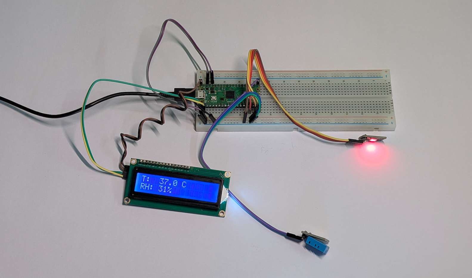
This video demonstration shows the DHT11 sensor capturing temperature data, which is displayed on the LCD screen. At the same time, the RGB LED smoothly shifts its color based on the temperature — transitioning from cool blue tones at lower values to bright red at higher values, creating a clear gradient effect from cold to hot.
What’s Next?
Step 1: Display DHT11 data on LCD & RGB LED (Completed)
Step 2 (Next): Add data logging & MQTT
Step 3 (Future): Local AI analysis + Web dashboard
Leave a Reply